


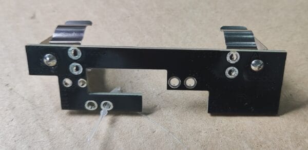
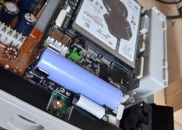



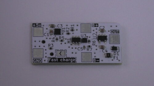
This mod board is installed on top of the original controller board which adds the following:
- Replacing original battery with Li-ion 18650 battery, with professional charging and protection circuitry.
- Replaces all old components like capacitor, resistor, and fuse which is now re-settable fuse.
This battery board will solve the problem of CMOS time keeping issue once and for all. The used battery should give more than enough charge.
Our test showed charging the battery for an hour will charge its voltage up by about 70-100 mV which our tests showed this amount could be enough for more than 6 months!
Notice that the Dreamcast BIOS has a limit of its own. It will ask for you to reset the time if you didn’t power the Dreamcast for a certain period (roughly one month). Battery mod solves battery issue but it cannot solve internal BIOS issue.
As above figure is showing, the battery follows the typical discharge rate and it passed 6 months and didn’t even go below 4v. This means extremely long battery life especially knowing the battery tested was an old Chinese knockoff so using a good original brand will show even better performance.
Installation tutorial
Quick installation guide
This serves as a quick guide to install the mod.
1- Desolder the original battery from the controller board, as well as, desoldering the fuse, capacitor, and resistor.
2- Put the pins in their places (in place of resistor, capacitor, and fuse) while having the black plastic on top of the controller board, then solder them one by one. After that, trim the pins from bottom to be flush. Check to make sure no shorts or excess solder bridging stuff.
3- Put the mod board on top of the 6 pins and solder it firmly. If you think the assembly will be tall and won’t fit when shell installed, then cut the black plastic before putting the mod board and soldering it. This saves you extra length but overall won’t be necessary.
4- Now the assembly is ready. install the ribbon cable on Dreamcast then carefully slide it in the boards assembly and install it. It is a tight fit but it fits perfectly fine.
5- Secure the board assembly with screws and install the battery, make sure of polarity to be correct which is very important.
6- Now everything is done, the rest is just to trim a plastic piece of top cover as shown in this image. this is to make sure cover closes perfectly fine and won’t push the battery. operation, look and feel won’t’ be affected at all. the spring will not be affected since the cut will be next to it, not where it hooks.
7- Close the shell and power on the console, set the time and wait for a minute or so. Now turn it off, then turn it on to verify that it retained the time. All done now.
Robin John Aldridge –
The installation is not difficult, even for a novice. It does require simple soldering skills. The fit in the machine is tight but did not prove an issue. I now no longer have to set the date and time. Great upgrade.
Dan (verified owner) –
I had some fitment problems with it, entirely related to the preinstalled pin headers used to connect Thunderdream’s board to the DC. The pins are aligned in a way that makes easy drop-in very difficult; it required a lot of very delicate manipulation with angled tweezers to bend the pins in such a way as to allow them to correctly align with the through-holes. It took me about ten minutes and a digital microscope (and a great deal of swearing) to get it done. Then I had to melt the solder on the topside of each connection to allow for stress relief in the joints – not an easy thing to do in those tight confines.
In addition, there’s almost NO room for the flex cable to thread between the OEM board and the new one. It manages, and it works, but it is really tight, and again, needed fine tweezers.
I’m charging the battery right now in an external charger, because the board itself doesn’t seem to be capable of charging the battery on its own – I left the battery in the DC overnight with the power on, and it wasn’t charged at all.
VEGETA –
Hello Dan,
– The pins are made so that you don’t need to do it by yourself, just heat them and position them. most people preferred this way, but you can cut them and use the original components instead, or even reuse them. Yes, it is not a very easy mod to do.
– Flex cable should be routed nicely, check online pictures of others. maybe melt the pins and move the board slightly to make 1mm extra room for it.
– The board charges the battery for sure, its the main job. You should be able to check it via multimeter by measuring the voltages.
contact me in discord for more of this, i need to make sure it worked for you as it should.
Vegeta
Daniel Yetman (verified owner) –
This is an update of my July 17, 2026 review. I’ve added a star onto the rating, and addressed a few issues.
Firstly – my points regarding fitment with the pre-installed pin headers remains unchanged. I did, however, wind up removing the headers, as I determined that the increase in height was what caused my battery charging issues:
The increase of approximately 2mm in height caused by the pre-installed headers causes the battery to contact the underside of the top shell of the Saturn, which introduces just enough pressure to force the battery out of alignment, breaking the charging circuit. Once I removed those headers and reinstalled the board so that it sat flush atop the SEGA controller board, my battery charged perfectly and maintained the charge.
Many of my minor criticisms remain, as well – however, I also realize that the Saturn has very little free space inside, and the only point of criticism I feel remains justified is the alignment of the connection vias on the new board – they’re large, but misaligned just enough so that it remains an exercise in patience and geometric precision to get everything installed perfectly.
All in all – it is a GREAT product, one that solves an annoying problem I’ve been dealing with since the late 90s, and is genuinely worth the money; it’s just not ‘flawless’.